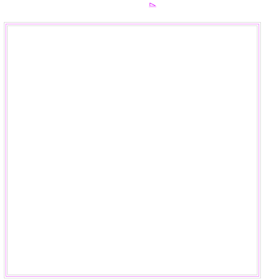
Building Silhouette and Depth Cueing
1. Modify, View, Linework. Start clicking building outlines. Use Detail Line (DL) where selection is not easy. 2. Visual style icon – Graphic Display Options. Depth Cueing
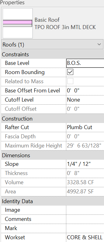
TPO roof
Create Roof within the walls so that the structure is attached to wall core. Structurally slope the roof ¼”/12” toward the rear side of the building for drainage.
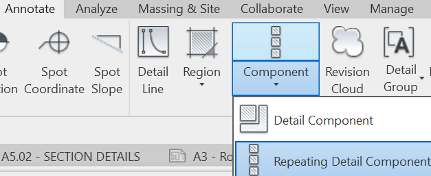
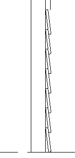
Repeating Detail Component
Use Repeating Detail Component on drafting views placed on sheets for siding, CMU, wall panels…for plan, elevation, or section details. Annotate, Component drop-down, Repeating Detail Component CREATE SIDING SECTION REPEATING DETAIL Create a family using Detail item. rftCreate, Detail, Line. Create a siding profile. Add two more.Create, Detail, Masking region – Line style: <Invisible…
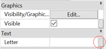
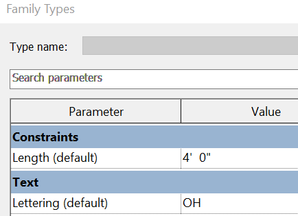
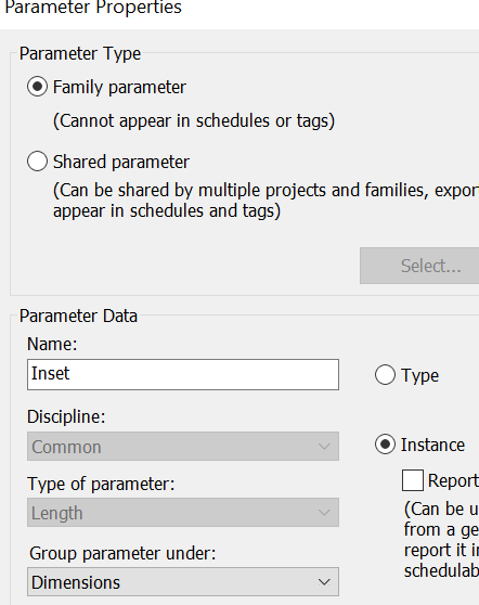
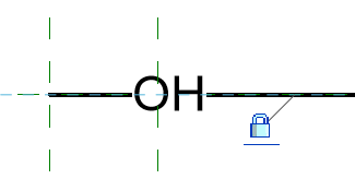
custom linestyle
File – New –Famaily – Annotations – Generic AnnotationCreate Label and name it as “Lettering”. Delete the red text notes.Create Label. Click empty space. Edit Label appears. Click the New icon.Click OK. Double click the “Letter”. Label Parameters added. Ok.Position the text to the center of the reference plane. Save. File – New – Family. English-I…
mass to steel frame
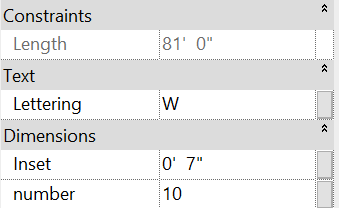
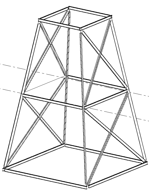
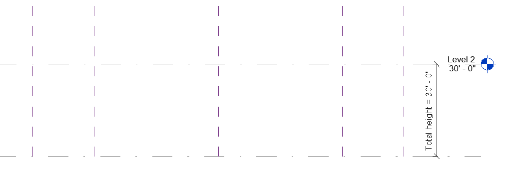
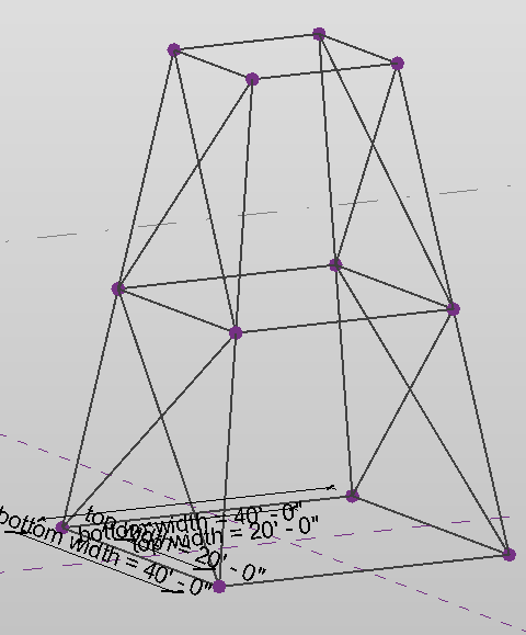
File – New – Conceptual Mass – MassSetup levels and reference planes.Add dimensions and lock them. Add dimension parameters; bottom width, top width, height Use Model Line tool to draw wire frame; lock lines on all 4 sides to reference planes. Create, Draw, Model. Draw the top at the level 2 *Draw top…
standing seam roof
The standing seam roofing is recommended for roofs having a slope of 1 in. per ft or greater. USE SLOPED GLAZING WITH MULLIONS 1. copy a roof and paste in the same place. Properties, select Sloped Glazing. Properties, Base offset from level: 1.5’ Grid 1 Mullions: rectangular mullion: select your custom standing seam mullion…
roof crickets w detail group
Structurally slope roof to the perimeter, 1/4″ per foot. Place roof drains at perimeters 6′-0″ from the edge and use the edge as secondary overflow. If not, use tapered insulation that is called roof crickets. Sketch roof cricket using Detail Lines. Create Detail Groups and re sketch the roof crickets. Finish Create Detail Groups with…
Hiding roof lines
Modify, View, Linework (LW) Select Invisible line. Click a roof line. You may change the line type and click the hidden line to change a line type.
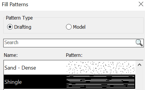
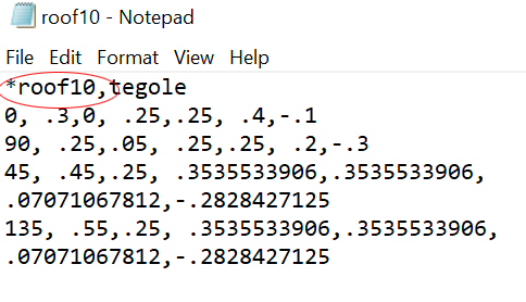
roof hatch
Roof Properties, Edit typeDuplicate the roof and rename it. Select “Asphalt shingle”. Graphics tap, Surface pattern *Surface vs Cut pattern Cut pattern will only show if you cut an object in Revit *Model Patterns remain a fixed size relative to the model, and Drafting Patterns remain a fixed size relative to…

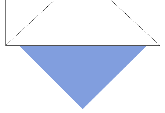
roof cricket
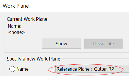
Go to 2nd floor plan view to see the chimney. Adjust the view range on Level 2. Create reference plane(RP) for cricket. Move the valley lines up 1” to use as a cricket slope. Create a Roof by Footprint ; Give slopes as the same roof slope to only the little 2 tiny edges. Finish.…
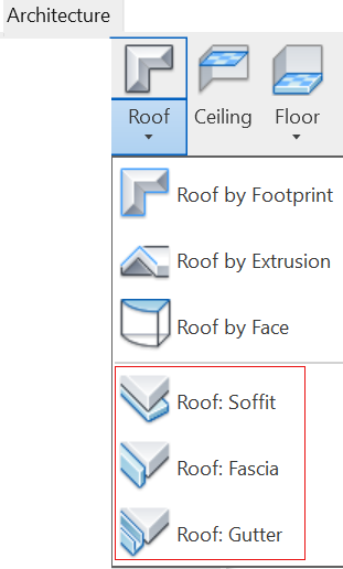
Soffit, fascia, gutter and downspout
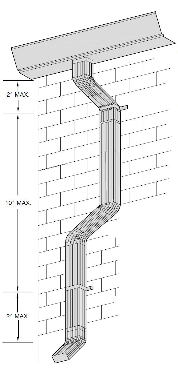
Install soffit, fascia, gutter, and downspouts in order Architecture, Build, Roof drop-down – Soffit Set view style to Wireframe to see walls. Select wall outlines and then the roof edges and close the sketch. Go to 3D view. Change the thickness and elevation. …
dropped ceiling
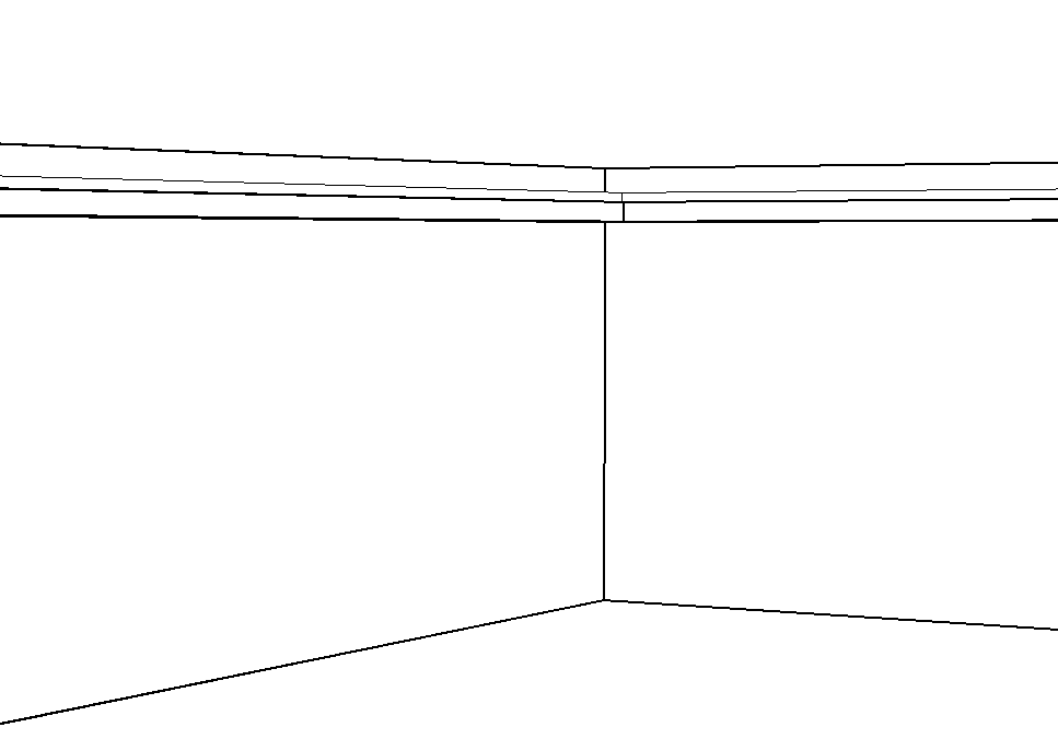
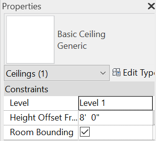
1. Create a ceiling and dropped ceiling in ceiling plan. Architecture, Building, Ceiling Height offset from the floor; 8’ Create dropped ceiling using sketch option with Height offset: from the floor 7’ Continue sketching another line with Offset -1’ (inward) in option bar. Finish. Check inside with camera. *set view range if…
parametric key map
Large floor plans can be broken up into different sheets and a key map is used as a map to denote which area is being placed on the sheet. One disadvantage of using key map is that they will need to be manually updated if the plan changes. 1. Edit your title block family. Draw…
Drafting view for Detail drawings
Create Drafting view for typical details master rvt file Drafting views are not associated with 3D. View, Create, Drafting view Open a sheet view. Drag and drop drafting views to sheets from a project browser. To rotate view, select the view. Option bar drafting views on multiple sheets Drafting views…
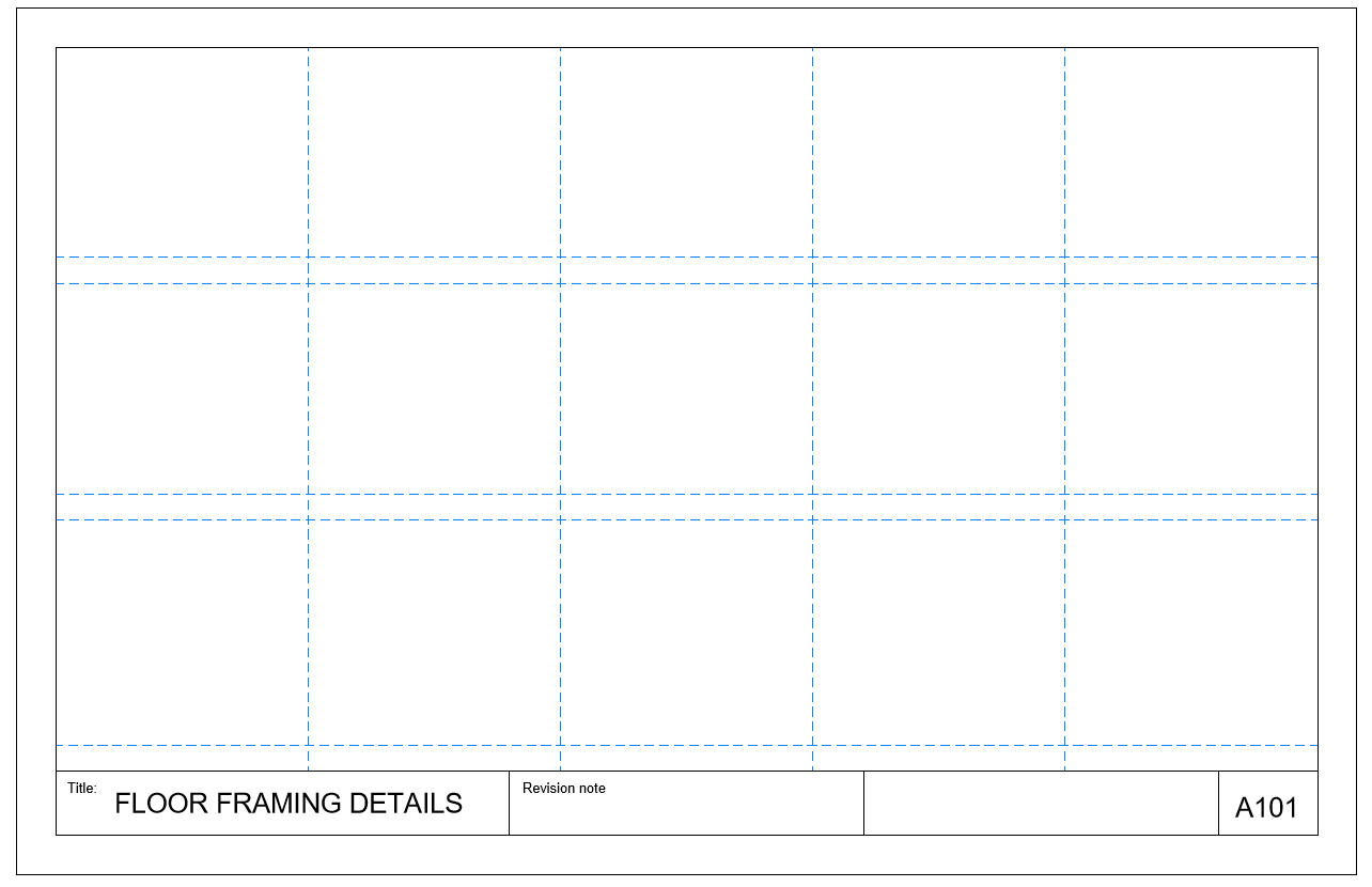
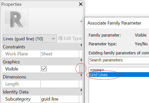
Guide grid in title block
For detail sheets, align detail views on sheets using guide grids, and then turn off the guide grid upon submittal or printing. Create lines (LI) for guide grid. Create a custom guide grid line style (VV) under Title Blocks. Convert lines to guide lines. 2. Add a parameter to the lines, which will allow us…
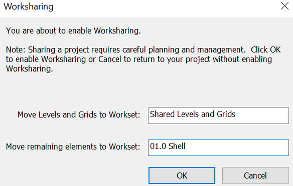
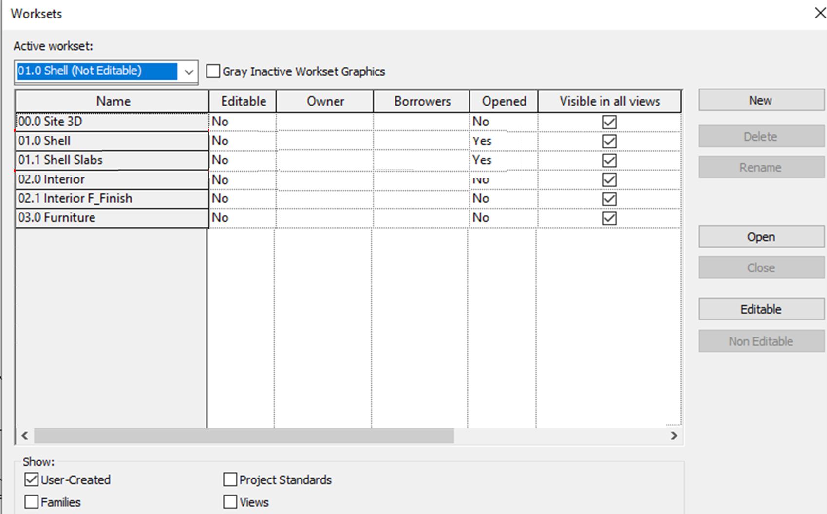
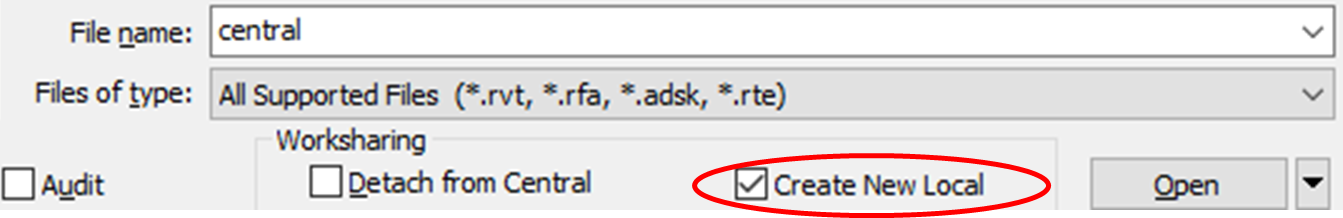
workshare
Central files are stored in a network drive. Each user creates local copies in local hard drives, and synchronize with the central. Since checking revit version without opening it is not easy, write down Revit version on the file name 1. Create a new workset and save it as a central fileCollaborate, Manage collaboration, Workset …
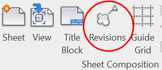
revision cloud
Create Revision sequence View, Sheet composition, Revisions. Add Show /Hide Cloud and Tag When you place revision clouds on sheets, tag it, and then select Revision sequence Annotation, Detail, Revision cloud …
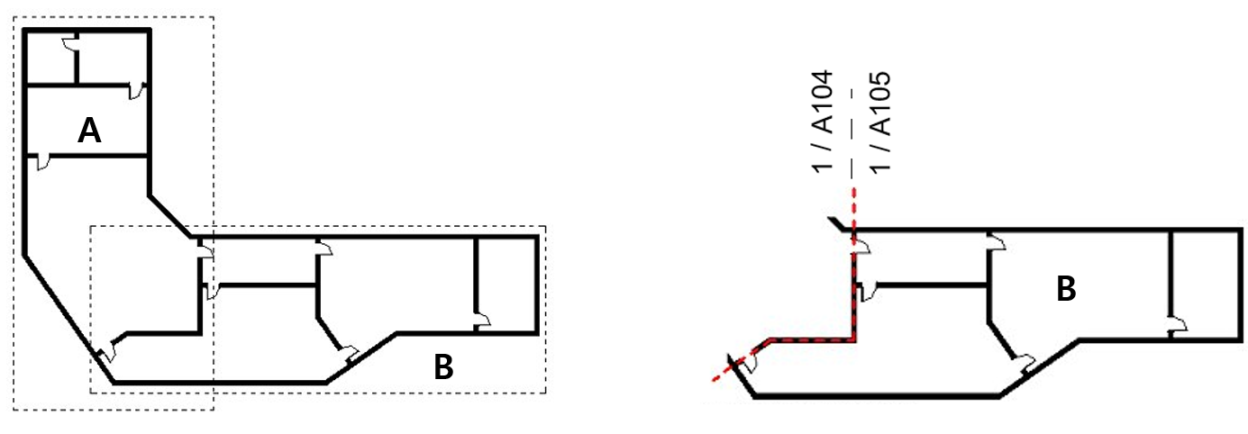
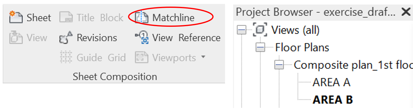
Matchline
Use Matchlines when the plan is too large to fit in one sheet.
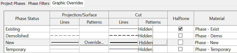
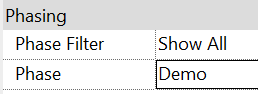
Phase
Display models based on project phase Existing, Demo, New construction Phase 1, Phase 2, Phase 3…. 25% CD, 50% CD, 75% CD, 95%CD, 100% CD2 properties of model elements; Object properties and Phase Manage,…
Electrical Symbols
1. Place 2D symbols on plan view Annotate, Symbol, Load family – Annotations – Electrical *Edit one of the inserted family and create your own symbol, and save them as family, and load into project 2. Create electrical legends
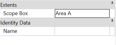
Scope box
Use Scope Box for enlarged portion of the views.Place scope boxes in plan views only, and can change its size and position in 3Dscope box vs section box Scope box define the extent of the elements visible within the 2D view while section box controls…
Section box
You can use a section box to clip the viewable portion of a 3D view. Go to 3D view. Properties, Extents, √Section box Go to plan or elevation view to modify the extents of a section box. Uncheck the Section box to hide it. Create a 3D working section Duplicate the 3D View and Rename…
Split face and paint
Split a surface such as wall or floor to apply different materials. Modify, Geometry, Split face In elevation view, select a wall surface and sketch a split line. The sketch should define a clear boundary to separate a surface. You can delete the split surface by clicking it and delete. Modify, Geometry, Paint *Create materials…
Starting view
Setup the default view when Revit opens; a Revit thumbnail view in file explore. Manage, Manage projects, Starting view
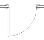
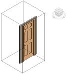
Door opening
Load family (CM). Doors – Door-Opening Properties, Edit type. Change the width and height.
brick lintel
Create a wall as a brick soldier course. Embed the brick soldier against the wall and cut geometry.
roof slope
Annotate, Dimension, Spot slope Option bar, Other than the option bar, you can move the grip to control the offset from the roof for specific elements. Properties, Edit properties – Leader line length to control the size. Round up Select element. Properties, Edit properties. Under Text, Unit format
roof slope unit
change roof slope unit from degree to pitch Manage, Settings, Project units Slope units: Rise/12”
Dimension style
Dimension arrowhead size Manage, Settings, Additional settings – Arrowheads
Title block
Create a family new Title block family. File – New – Family – Title blocks Save as family. Create your own title block. Add Texts and Labels. Insert images. Create, Text, Label Insert, Import, Image Load into your project. Go to Sheets in the project browser. To change the existing titleblock to the new…
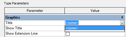
View title
Show/Hide view title Select the view title or the viewport. Properties, Edit type – Under graphics, Show Title – Yes / No / When multiple viewport When multiple viewport will show the view title only when there are more than one viewport in your sheet. When you don’t have a viewport title File – Open -…
Graphic scale bar
Annotate, Symbol, Symbol – Annotations, Graphic scale 1/4 or 1/8 Edit family.
Rotate a view on a sheet
Place the view on a sheet then select the viewport. On the options bar, select preferred rotation option. Or, Go to a view and select the crop boundary. Use the rotate command to rotate the viewport.
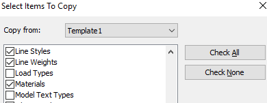
Transfer project standard
Open both of the project. Go to your new project. Manage, Settings, Transfer project standards Choose the source project and settings. If you open more than two projects, you can choose from which project to want to copy the settings. Duplicate types warning. Save the conflict list.
Create plan views
Create levels in elevation view. View, Create, Plan views drop down – Floor plan / Structural plan…
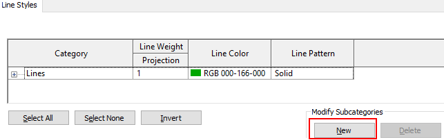
Create a new line style
Manage, Settings, Additional Settings. Click New.
Room tag box control
Right click on the room tag – Override graphics by category. Color: White
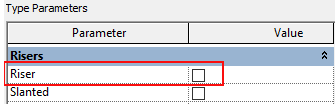
Stair
Architecture, Circulation, Stair. Draw stair using Create sketch for customized stair. Riser width 2′ 8″ Start offset: End offset: Uncheck Begin with Riser. Click the stair. Properties, Edit type. Middle support. Open risers.
North arrow
Detail components (break line, north arrow…) are 2D and view specific. Annotate, Detail, Symbol – Annotations – North arrow You can Edit the family and save as family. You can create a North arrow family from CAD file.
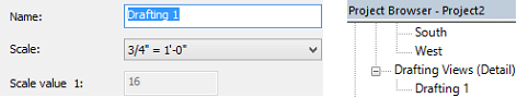
Creating drafting views
When you show details in a view that are not directly associated with 3D model, create a drafting view. View, Create, Drafting view This view is added under project browser, Drafting view. Place the drafting view to a sheet. Open a sheet view. Drag and drop the drafting view from a project browser to the…
Creating sheets
1. Right click at the Sheets in a project browser – New Sheet – Choose title block or Load. Many of the project information is already filled in there. You can directly click on the box and fill in. Date is global setting. Checker is not. 2. Drag and drop views to sheets. Or, View,…
Title block
Create a family new Title block family. File – New – Family – Title blocks Save as family. Create your own title block. Add Texts and Labels. Insert images. Create, Text, Label Insert, Import, Image Load into your project. Go to Sheets in the project browser. To change the existing titleblock to the new title…
Clearstory
Extend wall height and edit profile, and then place windows. Use 60″x18″ and 60″x34″ windows. Place 7 windows each. Edit families to place mullion in the middle. Also, edit the 60″x18″ window family to get 60″x34″ windows.
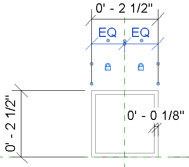
HSS
Create a Hollow Section Steel beam Create a family using Structural Framing – Beams and Braces. Edit the beam section as below. Put the dimensions when you have finished the extrusion. Lock the EQ dimension. Assign a steel material. Load into your project.
1. Foundation
Place the containers 3 feet apart on top of concrete pier foundations.
Best practices to reduce file size
Best practices to reduce file size : Purge models. Delete unused groups. Avoid exploding geometry Minimize the use of In-place families Minimize the use of void forms Use families rather than groups Maintain fewer links Link only in appropriate view. For example, a detail should be referenced to a detail view Use graphical symbols when…
CBT to TXT file printing
Go to this website and Plot/Print – Print CBP’s and more http://www.noliturbare.com/index.php
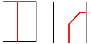
Cut profile
Use the Cut Profile tool to change the profile of elements in drafting view such as roofs, floors, walls, and the layers of compound structures. This is view view-specific; the model won’t change. View, Graphics, Cut profile The Arrow direction (→) will be shown.


 Duplicate types warning. Save the conflict list.